PRODUCTSSEMI DRY MACHINING LUBRICATION UNITS
Through-Spindle Lubrication Unit
Model No. MQ4-_31
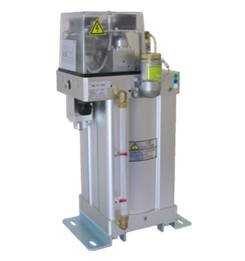
- MQL semi-dry machining (machining with lubrication using the minimum amount of oil) is useful in preventing environmental pollution.
- Even with a small-diameter tool that restricts airflow, fog is generated without bleeding air to the outside.
- Appropriately supports both large- and small-diameter tools with fog generation circuits in two systems.
- Ideal for lubrication with the center-through method, with which tools can be replaced according to the workpiece.
Standard specifications
| Operating fluid*1 | Oil-free clean compressed air | |||||||
| IN side supply pressure range | 0.2-0.8 MPa | |||||||
| OUT side (oil fog discharge) pressure*2 | Almost equal to the IN side supply pressure. | |||||||
| Withstand pressure | 1.2 MPa | |||||||
| Ambient temperature | 5-50°C | |||||||
| Viscosity of oil used*3 | ISO VG32-68 | |||||||
| Setting range of the number of shots | 1 to 60 shots/min (0.08 cm³/shot ) | |||||||
| Oil tank capacity | 1,000 cm³ (effective capacity) | |||||||
| Pipe connection threads | AIR IN | Rc3/8 | ||||||
| FOG OUT | Rc1/2 | |||||||
| Maximum airflow rate | Approx. 500 dm³/min (ANR) | |||||||
| Solenoid valve (PV, SV) consumption current | AC 100 V | 0.06 A | ||||||
| DC 24 V | 0.17 A | |||||||
| Protective structure (dust resistance and drip resistance) | Equivalent to IP54 | |||||||
| Weight | Approx. 10 kg | |||||||
*1. To protect the fog generation mechanism from greasy dirt, install an oil removal filter (oil removal filter Model F74C-3BD-ADO or equivalent) on the IN side. When using an oil removal filter, install a 5-μm filter upstream to extend the service period of the elements in the oil removal filter.
*2. The fog generation mechanism can generate fog with a pressure gradient of within 0.02 MPa and discharge fog at a pressure close to the IN side supply pressure.
*3. Select the type of oil whose viscosity will be 10 to 150 cSt during operation for Model No. MQ4-_31.
Notes:
- Oil feed checker on the oil supply route: The FC allows you to visually check pump operation because the check float moves with the oil pressure fed by the pump.
The proximity switch can also be used for electrical checks. - Level switch: The LS alerts the user that the oil has reached the lower limit.
- Semiconductor pressure switch: The MPS displays the OUT side pressure in digital form separately from the tool pressure lower limit alert on the OUT side.
(A DC 12 to 24 V power supply is required.)
 |
|
Model No.
| MQ4 | - | 0 | 31 | - | 1 | B | 0 | 0 |
| Product name | [1] | [2] | [3] | [4] | [5] |
[1]Oil supply method
| 0 | Manual oil supply method |
| A | Automatic oil supply circuit method |
[2]Rated voltage
| 1 | AC 100 V 50/60 Hz |
| 3 | DC 24 V |
[3]IN side accessories
| B | No accessories |
| C | Regulator |
| D | Filter/regulator |
[4]Inclusion of the monitoring and pump drive equipment
| 0 | Oil feed checker: FC (standard accessory to visually check pump discharge) |
| 2 | Proximity switch for monitoring |
[5]OUT pressure detection equipment
| 0 | Semiconductor pressure switch (digital pressure display, two outputs) |
| 1 | With mechanical pressure switch and pressure gauge |
Model No. MCA-0B_ _
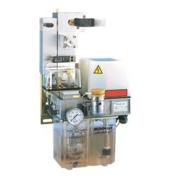
- The through-spindle lubrication unit is an oil atomization system for machining that turns oil into a fine mist and supplies it with air to the tool blade section.
- Performs machining such as cutting, grinding, drilling, and tapping using a tiny amount of almost-dry oil.
- Prevents ambient pollution due to coolant dispersion and eliminates swarf and the oil removal process of workpieces by enabling machining without circulating coolant.
- Prevents environmental pollution due to oil dispersion, dripping, or other causes through the ultrafine atomization of cutting oil and the supply of the optimum and minimum amount of oil.
- The latest machining method always keeps the site clean.
- Significantly reduces the time required to remove liquid from workpieces and swarf and associated costs.
- Minimizes the costs of disposing waste liquid and waste oil.
- Useful in extending tool lifetime, improving machining efficiency, and reducing running costs.
Standard specifications
| Operating fluid | Oil-free clean compressed air*1 | |
| Operating pressure range | 0.2-0.7 MPa | |
| Manifold pressure (pressure on the oil fog discharge side) | 0.05-0.6 MPa | |
| Pipe connection threads | AIR IN | Rc3/8 |
| FOG OUT | Rc1/2 | |
| LIQUID OIL OUT | Connection of a tube with an outer diameter of Ø4*2 | |
| Viscosity of oil used | ISO VG32-68*3 | |
| Setting range of the number of shots | PV1, PV2 | 1 to 60 shots/min |
| PUMP1 | ・0.05 cm³/shot ・0.08 cm³/shot |
|
| PUMP2 | 0.05 cm³/shot | |
| Oil tank capacity | 1,000 cm³ (Effective oil capacity: Approx. 800 cm³) | |
| Airflow rate | 500 dm³/min max. (ANR) | |
| Rated voltage | ・AC 100 V ・AC 200 V ・DC 24 V |
|
| Ambient temperature | 5-50°C | |
| Weight | Approx. 7 kg (without adjustment equipment) | |
*1. If oil may enter, install an oil removal filter (oil removal filter Model F74C-3BD-ADO or equivalent) to protect the fog generating mechanism from dirt.
When using an oil removal filter, install a general filter for air pressure (5-μm element) upstream to extend the service period of the elements in the oil removal filter.
*2. Included only with the oil discharge type.
*3. Azbil TA Co., Ltd. provides the recommended oils shown below.
Select the oil type whose viscosity will be in the range of 10 to 150 cSt while the lubrication unit is operating.
・Unicut Jinen MFF (multifunctional oil VG32)
・Bredor Special (plant oil, VG38, FDA-compliant)
Model No.
| Main model No. | Adjustment equipment | Discharge pump | Bypass and vent valves | Oil feed monitoring | ||
| IN side | OUT side | For fog(PUMP1) | For liquid oil(PUMP2) | |||
| MCA-0BH3-_BB4 | None | 0.05 cm³ × 2 series | None | Bypass: Low differential pressure RV
Vent valve: Included Included |
None | |
| MCA-0BH3-_BB6 | None | 0.05 cm³ × 2 series | None | Included | ||
| MCA-0BB3-_BB4 | None | Included (0.05cm³ ) |
Included (0.05cm³ ) |
None | ||
| MCA-0BB3-_BB6 | None | Included | ||||
| MCA-0BB3-_SB4 | F/R | None | None | |||
| MCA-0BB3-_SB6 | F/R | None | Included | |||
| MCA-0BB3-_DB4 | F/R with solenoid valve | None | None | |||
| MCA-0BB3-_DB6 | F/R with solenoid valve | None | Included | |||
| MCA-0BB3-_CB4 | F/R | Ball valve | None | |||
| MCA-0BB3-_CB6 | F/R | Ball valve | Included | |||
Notes:
- A pressure gauge for the filter/regulator is included with models with a filter/regulator.
- A discharge pump for fog with 0.08 cm3/shot is also available.
- Models without bypass and vent valves are also available.
- The manifold pressure gauge, oil level switch, and 12P terminal block are standard accessories.
|
|
Model No.
| MCA | - | 0B | B3 | - | 1 | B | 0 | 3 |
| Product name | [1] | [2] | [3] | [4] | [5] |
[1]Pump discharge amount
| B3 | Fog: 0.05 cm³/time Oil: 0.05 cm³/time |
| B4 | Fog: 0.08 cm³/time Oil: 0.05 cm³/time |
| H3 | Fog: 0.05 cm³/time × 2 series |
| H4 | Fog: 0.08 cm³/time × 2 series |
[2]Rated voltage
| 1 | AC 100 V 50/60 Hz, AC 110 V 60 Hz |
| 3 | DC 24 V |
[3]Inclusion of the supply air adjustment equipment
| IN side | OUT side | |
| B | No accessories | No accessories |
| A | No accessories | Ball pump (CHBF) |
| C | Filter/regulator | Ball pump (CHBF) |
| D | Filter/regulator with solenoid valve | No accessories |
[4]Bypass valve model and whether the vent valve is included
| Bypass valve model | Includes vent valve | |
| 0 | Solenoid valve | Yes |
| A | Regulator | |
| B | Constant differential pressure regulator |
[5]Accessories
| Includes pressure switch | Includes oil feed monitor | |
| 3 | Operating pressure side and manifold side | No |
| 4 | Manifold side | |
| 5 | Operating pressure side and manifold side | Yes |
| 6 | Manifold side |